What follows is the result of a lot of research, discussion with the collective minds of some notable inhabitants of the VOLT (and Florida) Facebook pages, chatting to V-dub experts and general tinkering. I am in no way a qualified mechanic (I’m actually a teacher) although I am a ‘time served’ Air-cooled VW nut with a 30 year history of building, driving and messing about with the oily (and rusty) bits of Beetles, T2s and the like.
Having said that, if you do any of the things I suggest below and anything blows up it’s not my fault!

Diesels are very different beasts compared to a petrol engine, but as long as you know one end of a spanner from the other there is no reason why you shouldn’t find some (if not all) of what follows applicable or indeed achievable with regards to your own engine. I’m not claiming to be a pioneer in any of this but I’ve been asked to pull all this information together in one place here as a blog post. Facebook is great for some things but information can be hard to find and it’s not often all in one place. Hopefully someone will find it useful! Most of this will be applicable to all the turbo charged 2.4 Diesel engines. I’ll mention the intercooler part later related to the ACL version of the engine.
Now this has turned into a bit of a lengthy tome to say the least so here’s a summary of what I ended up doing:
- Check the pump timing
- Fit an EGT, Boost and Oil Temperature gauge
- Fit exhaust wrap and a Turbo Blanket
- Fit an additional oil cooler
- Modify the Boost relief Valve
- Add a manual boost controller
- Add a ‘Boost Ring’ (possibly)
- Modify or remove the nylon spacer
- Turn the boost pin to max ramp (and then adjust after testing)
- Turn the start wheel down 270 degrees
- Turn the ‘Stop screw’ (AKA smoke screw) clockwise 1 turn
- Set boost to 1 Bar (ish) (1.2 Bar with an aftermarket intercooler)
- Possibly fiddle with the fuel screw if you’re brave.
- Adding a larger intercooler and pipework
That’s what I did in a nutshell. If you need more info… then read on!

FLO
Before we delve into the engine stuff I thought I’d introduce the vehicle I’ve been modifying. I am fortunate to own a 1994 VW LT31 Westfalia Florida. I’ve done lots of other stuff to it whilst I’ve owned it but I’ll concentrate on the greasy stuff here. If you’re interested in seeing more of the van you can find it on Instagram as westfalia_florida_mods
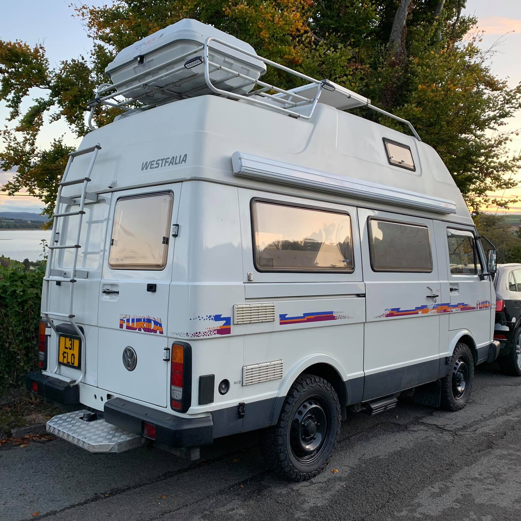
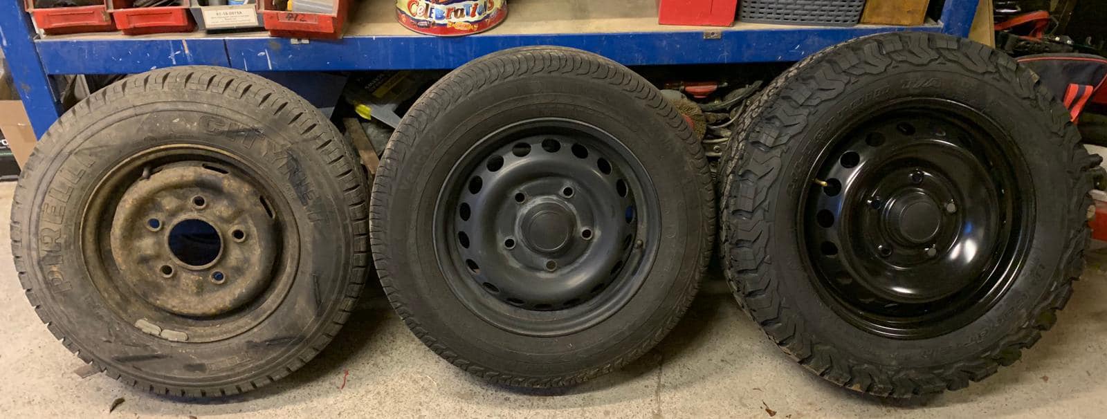
This particular LT is fitted with the highest final drive (meaning lower revs at ‘high’ (er) speeds). This is great for noise, engine wear and fuel economy (a relative term in an LT!) but means hills can be more of a struggle. This is compounded by the fact I have fitted larger wheels and tyres. The LT came from the factory with dinky 14″ wheels. Nowadays it’s fairly common to see them with ‘lifted’ suspension and wheels from Ford Transit Custom vans and chunkier ‘All Terrain’ tyres. Most popular are 15″ and 16″ whilst I chose to fit 17″ rims with 225/65/17 BF Goodrich K02 tyres.
Combined with the fact that the Florida is a heavy beast and that I drive up a lot of hills meant I decided I wanted to do some engine work.
AIMS.
I don’t want to go ‘fast’; just ‘less slow!’
In a vehicle the size and height of a Florida, ‘Top Speed’ isn’t really something I care about. Coming from regularly driving a ’73 Bay window (albeit one with a mildly modified engine) I’m more than happy at 55 / 60mph tops.
I also live up a hill where I had to trundle up in 1st gear as I couldn’t get enough momentum to get the turbo to kick in enough to change up. This was my first target! Torque is what I wanted. Low down ‘grunt’ and the ability to climb up hills without having to wring out the gears. I wanted the turbo to spool up at lower revs effectively giving me more torque where I wanted it. Remember: once the boost was ‘on’ there was ‘enough’ power… I just wanted it sooner.
RESEARCH.
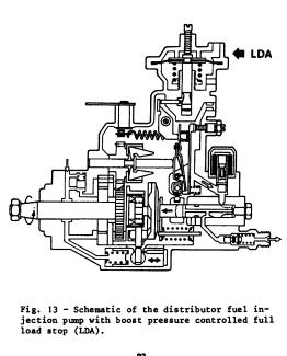
Before undertaking any modification to the engine I set about reading up on the subject. The VOLT and Florida FB pages were a great source of information along with The Brickyard forum. You’ll also find information by lurking in the worlds of Land Rovers and old Volvos (the latter with which the LT shares an engine). The main part of the engine you are modifying is the part which controls the amount and timing of fuel that enters the engine dependant on the amount of boost that is being produced. This is the LDA.
This is common on lots of different engines in lots of different vehicles with all sorts of capacities and numbers of cylinders. This meant there’s plenty of info available about them.
Knowledge is power! The three main places I found useful were:
How to make your 2.4 LT1 faster on The Brickyard by Chris DeLong (AKA Rabbit 16V). Chris has a variety of LTs in America and knows what he’s talking about.
Understanding and tuning the injection pump (from a Landrover forum) which goes into loads of technical details. This is a PDF.
Pump Modifications . This is a quick and simple guide to tuning the LDA. Not everything is applicable to the LT but it’s a good start and you can see what stuff looks like.
PREPARATION.
Pump timing
Before we delve into the tuning and supporting modifications you should make sure everything is working as it should. No amount of fiddling with settings are going help if the engine isn’t working as it should as stock. Make sure everything is serviced properly too. A sure fire way to discover anything that’s on the brink of breaking is to start tuning it!
This includes checking the timing of the pump. This involves the use of a specific dial gauge and some skills. I bought my NOS dial gauge online for a good price. It’s worth shopping around. They are also available from the usual places including Brickwerks. They certainly aren’t cheap and it’s not something you’d use everyday. You might want to ask around and see if you can borrow one unless you have a tool collecting fetish (guilty as charged).

To be honest; if your van is starting and running properly you could probably skip this part if you feel it’s not something you want to delve into. I was interested in what mine was set to. Stock, the ACL ‘point of injection’ is 0.85 +/- 0.2. When I checked mine is came out at 1.00. It was running well and there was no visible smoke at all so I left it where it was. I might revisit this at a later date though.
GAUGES
Rev Counter
My van came with a MPG speedo (swapped when it was imported) and a time clock incorporating a fuel gauge and water temperature gauge. VW thoughtfully also supplied LT owners with 3 blank spaces to add additional dials.
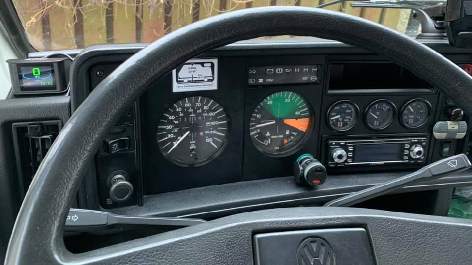
My first job was to search for a factory ‘Rev Counter’. These are one of those strange ‘Holy Grails’ of the LT world (along with opening quarter light windows.) Aside from looking cool these are also rather useful. You can keep an eye on the engine speed and once you are ‘in the green zone’ you know the turbo is going to kick in. Alas, this doesn’t help to make it come into play any sooner! If you’re lucky these are ‘plug and play’. You ‘simply’ remove the dash pod and swap everything across. Sounds easy if you say it quickly 🙂
Now I knew how fast I was going and how fast the engine was turning I needed some ‘non factory’ gauges. Whilst I was elbow deep in the dashboard I added an auxiliary fuse box powered by the ignition switch. This means running power to extra stuff in the dash was easier and safer (including my reversing camera and USB charging points etc). You’ll also want to connect up the lighting circuit too, so you can see them at night. Sort out a suitable earth point while you’re there!
Boost
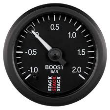
I was going to be increasing the turbo boost (forcing more air into the engine). You don’t really need to know how much boost you’re getting when everything is stock. At factory it just works. When you plan to increase and adjust your boost it’s important to know how much you’ve ended up with. You can get all sorts of gauges both ‘mechanical’ and ‘digital’. After some brief dabbling with digital gauges I decided I preferred to keep in analogue and chose a STACK gauge. They have a good reputation and I could get a matching set for all three. This particular gauge involves the common method of adding a ‘T’ into the pipe which carries the boost signal from the intake manifold to the top of the LDA.
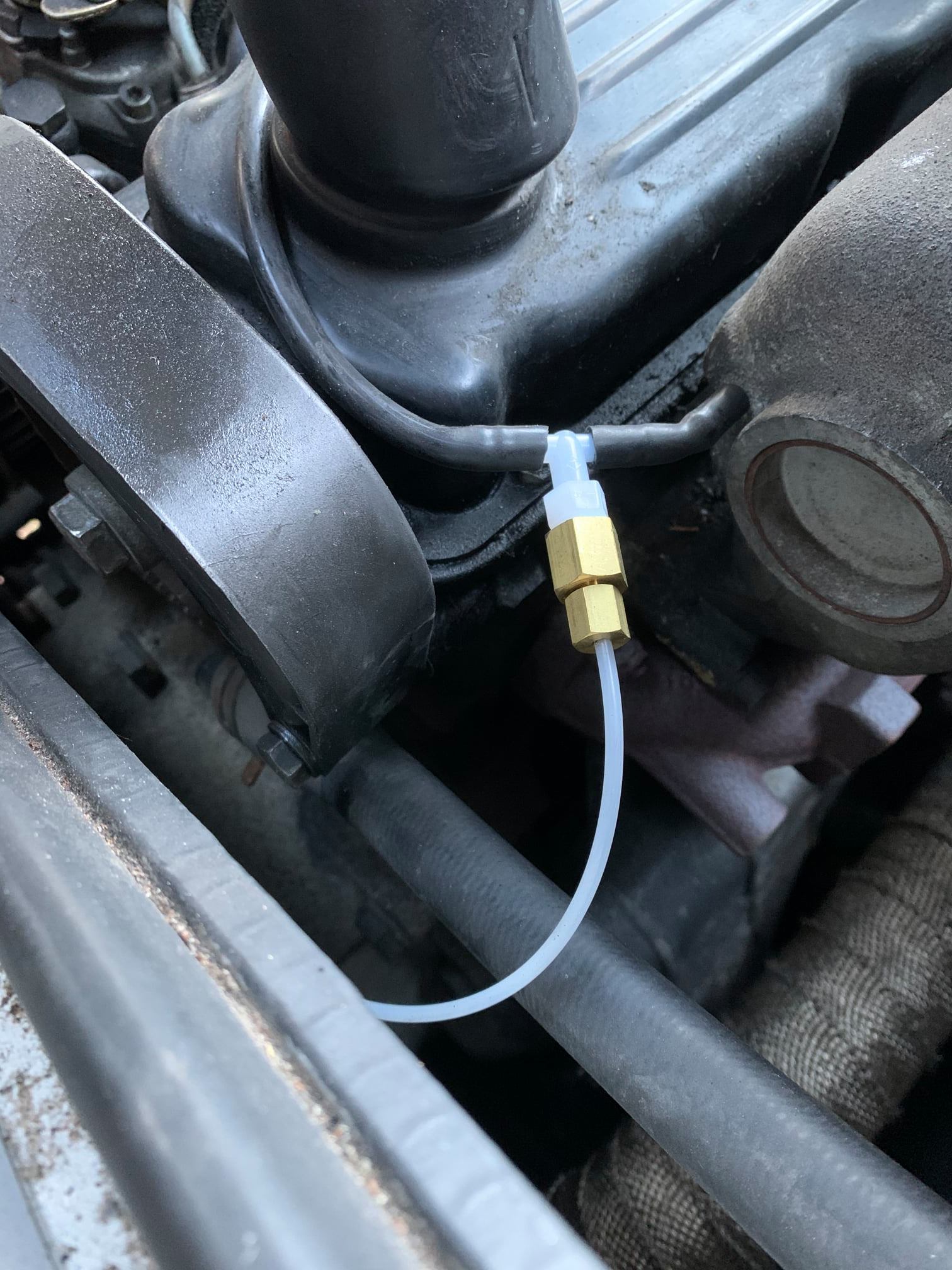
Take care with the ‘signal’ hose. It comes coiled up and you should avoid kinking it! I ran mine around the edge of the engine bay (around the nearside) and carefully threaded it through to behind the grill and through a hole fitted with a suitable grommet. You should ‘just’ have enough. BAR or PSI is up to personal choice. I went with BAR. Don’t be surprised when it appears to not work when you try it… you have to be moving and the engine under load for it to function – and don’t forget to remove the transportation clip!
Oil Temperature
VW supplied us with oil pressure warning lights and a water temperature gauge. Incidentally; if you are having trouble with your water temperature gauge then check the relays. Leaking windscreen rubbers or indicator housings can let water onto/into these and the resulting dampness can result in some weird results. Drying them out can cure this easily. Fixing the cause of the leak can be more problematic!
When we are tuning the engine we will be adding more fuel. More diesel means more heat. Most of the modifications listed beneath are linked to this. You’ll want to keep an eye on your oil temperature. You want it to heat up quickly so it’s effective and then stay within an appropriate range. The water temperature gauge isn’t really ‘quick’ enough to tell you when things are getting too hot (actually the oil one is pretty slow too!)
There are two parts to this. The ‘sender’ and the ‘gauge’. Again – you can choose the units of measure and I’m sure there are arguments for both. You choose which one you prefer. I went with Degrees Celsius with a 60-150 range.

For the sender you again have choices. You can buy a ‘T’ fitting and use an existing oil pressure switch ‘port’. You can also purchase a suitable threaded drain plug to fit the sender into.
Just make sure you do your research into thread sizes to suit if you go with this method. You’ll need to make sure it fits into the block or sump and the sender fits into the adaptor.
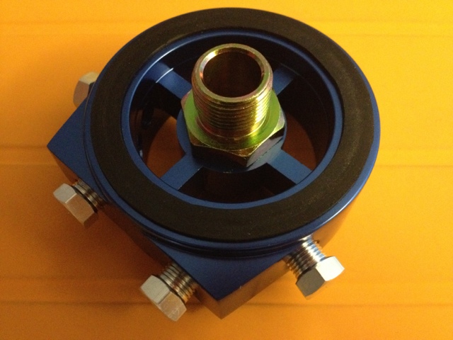
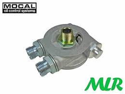
Initially I didn’t use this method. Instead I used a ‘sandwich plate’. In fact I used two (but more on that later). These are commonly available online and ‘sandwich’ between the engine and the oil filter. They come with various outlets into which you can add a variety of senders. I only used one ‘port’. it turns out that STACK Degrees Celsius gauges come with a metric threaded sender.


I had to order an additional sender with a 1/8npt thread as this is what is commonly on the sandwich plates. Autometer (who own STACK) sell a suitable one. You might find a generic sender works too but when it comes to these kinds of things I tend to buy them from the same supplier. That way if it doesn’t work it’s somebody else’s mistake!
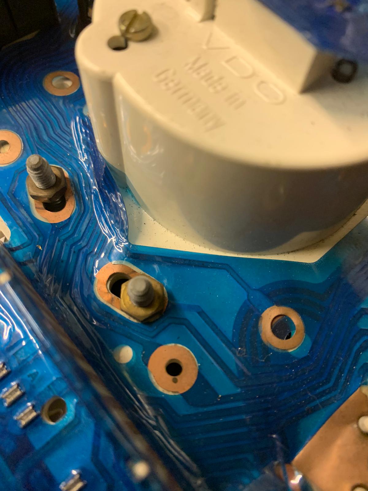
The oil temperature sender needs a good ‘ground’ (connection to the chassis). This had me puzzling for a while before I worked out why it wouldn’t work when in the painted sandwich plate. A simple solution was to add a wire to the body of the sender. I did this with a ring terminal under the sensor and a wire to a suitable point on the chassis. I’ve also seen it done by clamping a wire with a jubilee clip to the sender body too. A good ‘earth’ ensures an accurate reading. Then you run the signal wire up to the back of the gauge. Again; make sure you use grommets in all the holes.
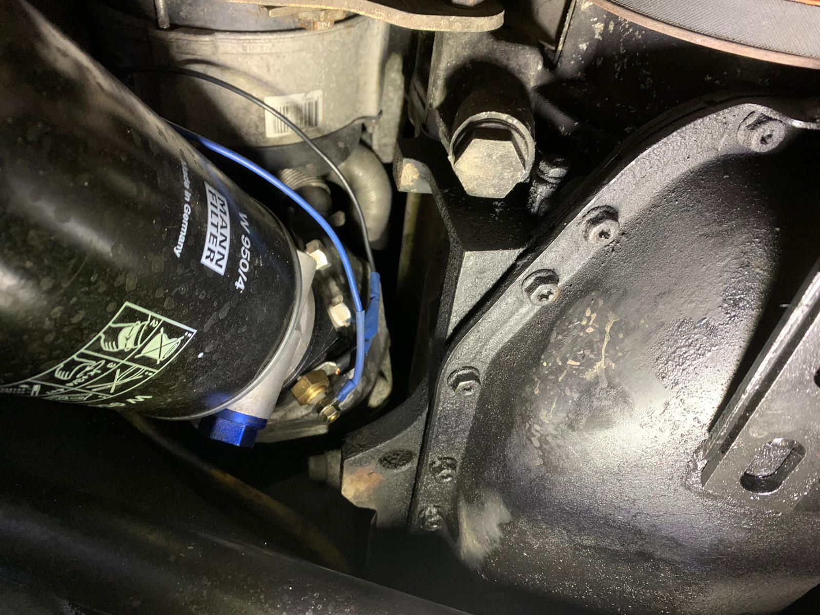
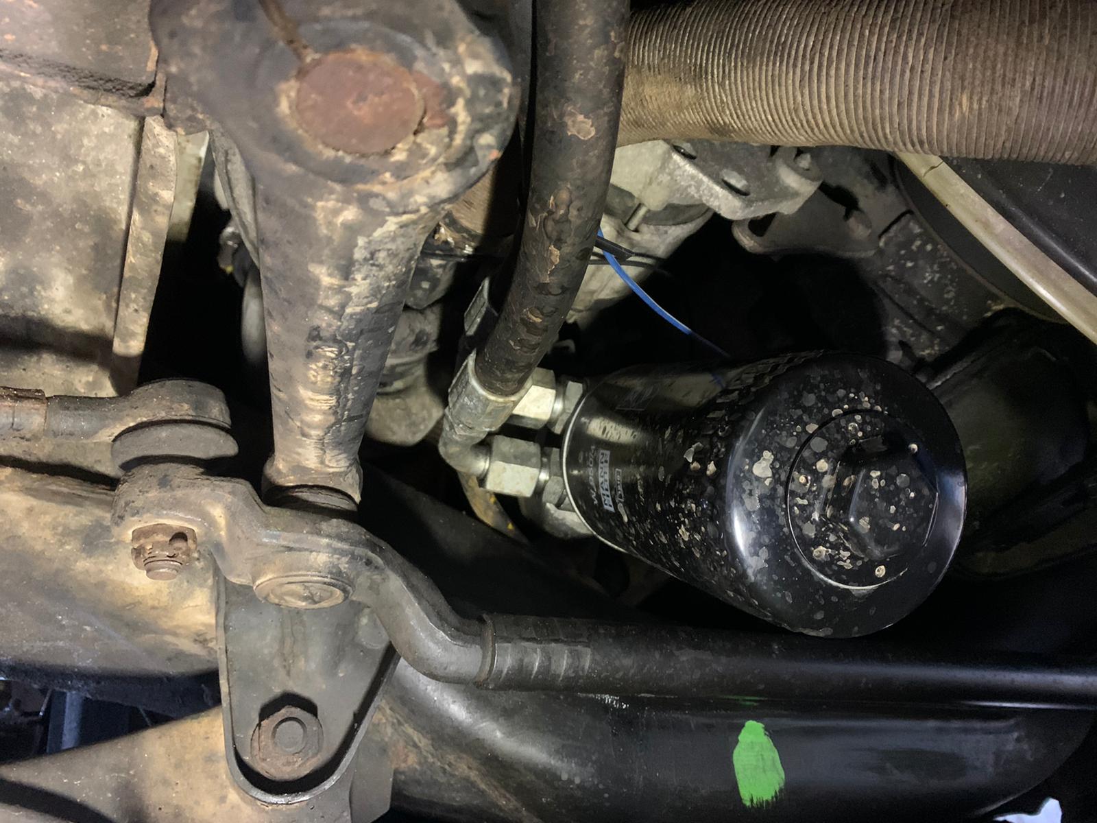
4X4 owners will have less space around here and will (apparently) need to use a shorter filter as it’ll hit ‘stuff’. If you’re adding an oil cooler plate here you might need to put your sender elsewhere to fit everything in. The black plate is the one with the sender ports in it. The silver one is the oil cooler adaptor (see later).
The blue wire is the signal wire running to the gauge. The black wire is attached to a ring terminal under the sender and attaches to the body of the van to give it a suitable ‘earth’. Try and avoid running your wires near to the alternator wiring as it can cause interference.
**After using this method for a while I found myself battling with a relentless oil leak from the sender sandwich plate. Despite a couple of attempts at resealing it I ended up removing it and fitting the sender into a modified sump plug. There’s plenty of debate about which location is better.**
Exhaust Gas Temperature (EGT)
I’m going to say that this is the most important gauge. Too hot oil or too much boost isn’t good but too high exhaust gas temperatures for too long is going to melt something expensive. As you’ll see later you can quickly see temperatures that are close to or exceeding ‘safe’ amounts. This is one area which is the opposite to petrol engines. When a petrol engine runs ‘lean’ (less fuel and more air) it runs hotter. Then a diesel engine is ‘lean’ it runs cooler. As with all engines it’s all about getting the mixture correct under all conditions.

‘BANKS’ are an American firm specialising in tuning Turbo Diesels. This is an interesting article on the subject (if you ignore the sales pitch at the end). There’s lots to digest on why EGT is so important to consider, what increases them and how we can reduce them. Whilst the LT is never going to be a race car, the theory still applies. There will be tons of folk tuning diesel engines (‘rolling coal’!) who probably don’t give a second thought to their EGT. I personally prefer to know what’s going on.
So we need to measure the temperature in the exhaust as it exits the cylinders. This gives us the most accurate idea of what’s going on in the engine at combustion. The next question is pre or post turbo. After reading up on the subject I decided that ‘pre’ was the best option for accuracy (the action of the turbo itself cools the EG temperatures resulting in a falsely lower figure). This meant drilling and tapping cast iron. Not a particularly easy thing to do especially as I didn’t want to remove the exhaust manifold unless I really needed to.
The EGT sensor requires a 1/8″ NPT thread to be ‘cut’. The ‘NPT’ part tells us it’s tapered – it isn’t ‘straight’ – and this is to our advantage. It’s easier to tap a tapered thread. After speaking to an engineering friend who does this sort of thing all day, he recommended that I drilled an 8.8mm hole to tap into. Technically it should be an 8.7mm but the extra 0.1mm would make it less likely to snap the tap off in the exhaust!
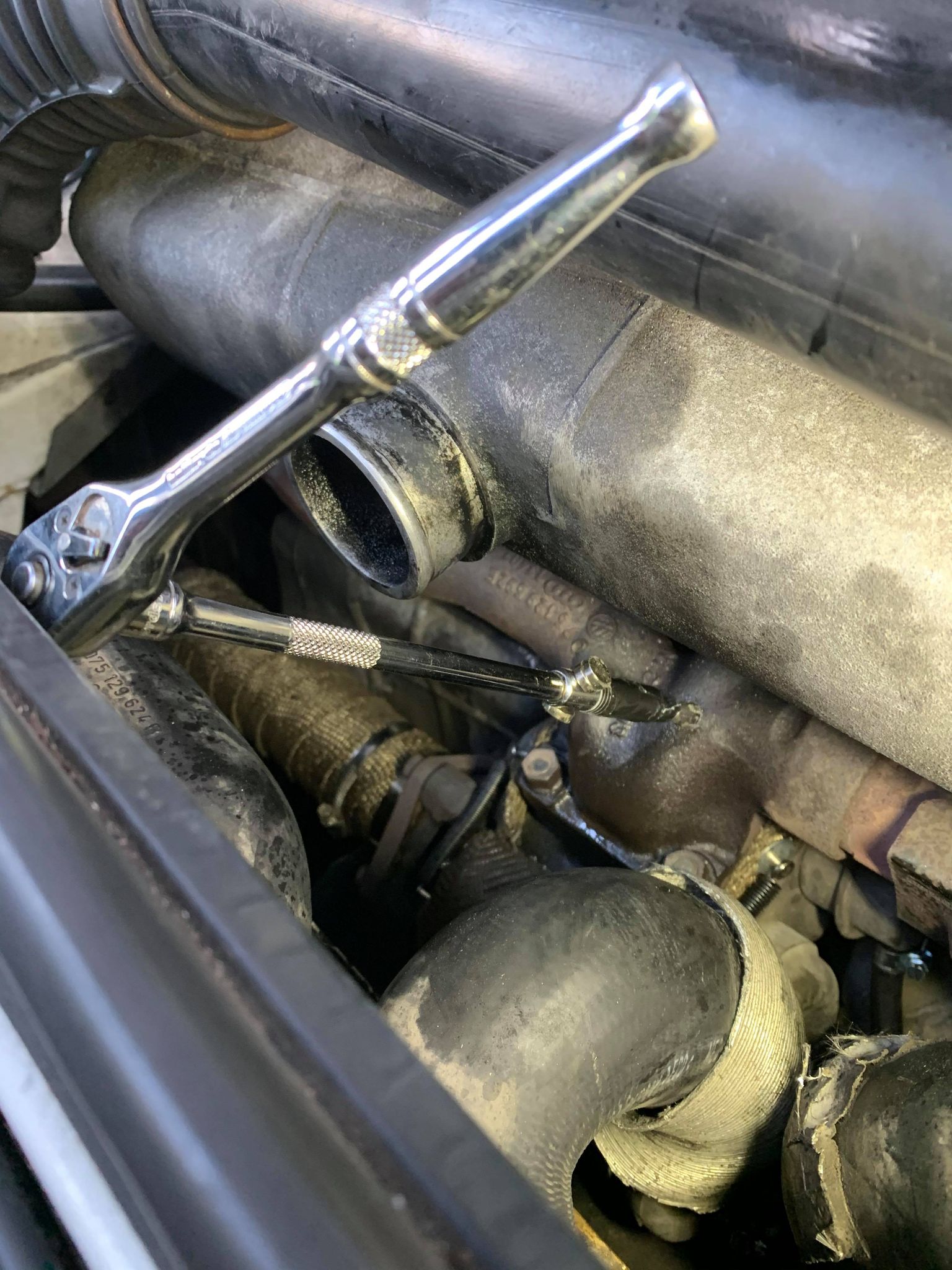
Drilling cast iron isn’t easy so you’ll need a variety of sizes of quality drill bits (don’t be tempted to use that set you got in the ‘middle of Lidl’ when you were last shopping). Centre punch your mark and start small. Use something like WD40 to keep the drill bit lubricated and go slow. I found that I could just about squeeze my cordless drill in the space once I’d removed the hose from the intercooler. I also put a selection of strong magnets around the drill bits to attract swarf. I used a ‘pen magnet’ to clear up any metal shavings as I went along (including inside the exhaust manifold once the hole was big enough). Work your way gradually up your drill sizes.

Once you manage to get up to the 8.8mm sized hole you can reach for the tap. There’s not enough room to get a ‘normal’ tap handle in here so you’ll need to get creative. I used a ratchet with an extra long extension, a suitable socket (with some gaffa tape to stop the tap falling out) and more magnets to attract the swarf. Some engine oil is a good lubricant this time. Cast iron is self lubricating (according to my engineer mate) but there’s no harm in adding some more and it helps give the metal ‘dust’ something to stick too. You REALLY don’t want any of that stuff in the turbo! Go slow and keep backing the tap out and cleaning off the metal. DON’T tap the whole length or the sensor fitting might not tighten up as it’s tapered! Keep checking!
Once you have you your hole tapped and everything cleaned up you can screw in your NPT fitting, snug it down and breathe a sigh of relief. How the probe is fixed is dependant on your chosen sender / gauge combination. I chose a STACK gauge again and this uses a tiny grub screw. You can get two types of STACK EGT gauge (both available in Degrees or Fahrenheit). I went for the cheaper model. The more expensive one has options to add external switches and warning lights etc. I ran the wire around the engine bay, beside the expansion tank for the coolant and up to behind the dash. You can’t cut or modify these wires due to the way they work.
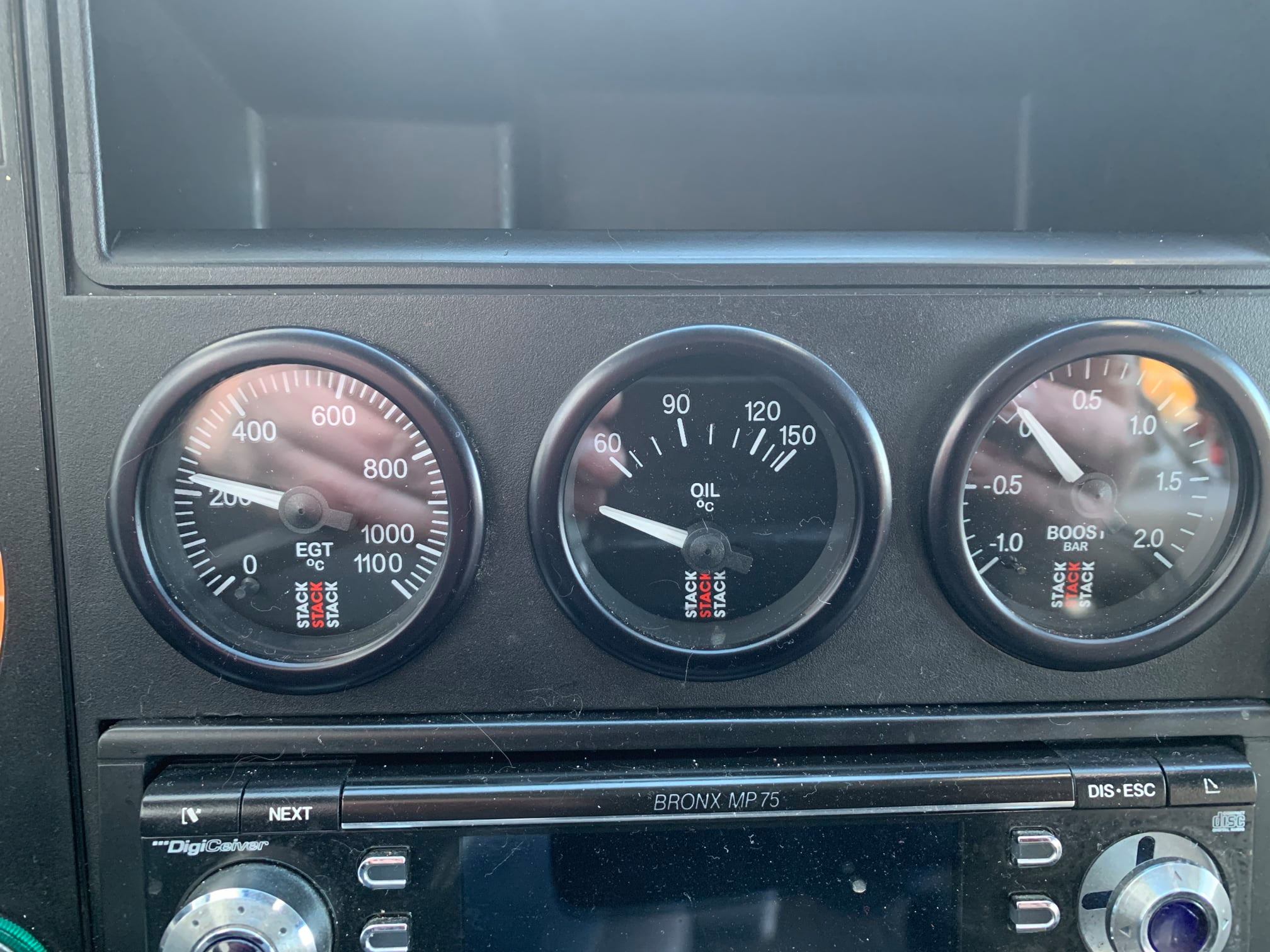
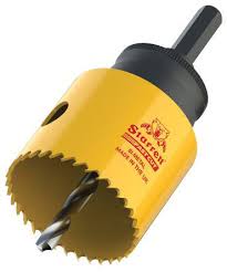
What order you put your gauges in is up to you. Be aware that the middle one is slightly obscured by the steering wheel. I put EGT right in front of me. The left hand ‘space’ is covered by a blanking plate and unscrews. This is where the factory put a clock if you had a rev-counter. The other two holes you’ll need to cut out with something suitable.
HEAT PROTECTION
As mentioned earlier; I was going to be adding more fuel and consequently creating more heat. More heat and more pressure in the turbo is a good thing (but not too much obviously!) The heat and pressure is what spools the turbo up and creates the boost. We want to make sure that the heat stays where it is supposed to be. You want to avoid raising the temperature of the engine ‘bay’ (although you’ll agree it’s a pretty unusual setup in an LT!)
Exhaust Wrap
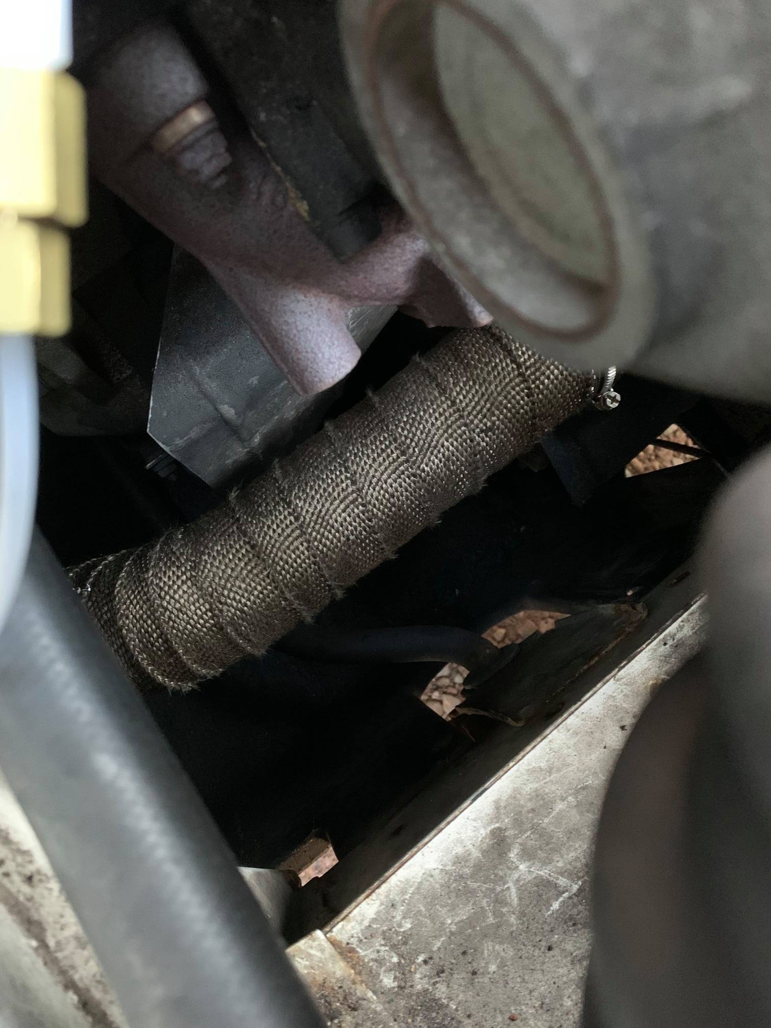
This is really easy to get on Ebay / Amazon etc. You simply wrap it around pipes and it keeps the heat in. Mine came with metal ties which were pretty rubbish. I used stainless jubilee style clamps on either end to secure the material as well. You can soak it in water first to help make it more pliable but I didn’t need to. I wrapped my exhaust from the turbo to where the pipe existed the engine ‘box’. It’s really itchy so wear gloves!
Turbo Blanket.
Now I was starting to feel like a real boy racer! These serve the same purpose as the exhaust wrap but they snuggle around the Turbo housing. Again – easily available on Ebay /Amazon etc. You could probably get a ‘kit’ with both the blanket and wrap. When you are searching it’s the ‘T3’ size you need.
You get ones with different attachment methods. Mine has springs. Due to access and placement this is awkward to fit but I got there eventually. You have to squeeze it behind the housing and then pull it though and down the sides. You’ll also have the turbo wastegate actuator rod to contend with.
Oil Cooling
Now this is something that will be of benefit to anyone really. Keeping your oil cool when you’re in warm weather, towing, driving up hills, fully loaded with the family and their camping stuff or all of the above is a good idea.
Coming from the Aircooled world I’m not even going to mention what type of oil you should be using. That never ends well!
You can buy kits for this online and this would be a good choice if you aren’t able to source parts yourself. I put together my own kit but the outcome is the same either way. Where you put your ‘oil cooler’ is up to you and if you search on VOLT and the FLORIDA pages you can get some ideas of where other folk have put theirs (you’ll just need to ignore the posts about fridges on the Florida page!)
I put mine in the centre underneath the ‘box’ where the fresh air enters the heater. I’ve seen various methods to attach these ranging from simple angle brackets bolted to the sides of the box to rubber mounted, multi point creations. I had a bit of a ‘moment’ here after I initially fitted mine and started over-thinking its orientation. Mine has the ‘ports’ facing down. As it turns out, whilst this setup isn’t the optimum it works just fine. It does make prefilling the radiator impossible but I can deal with that.
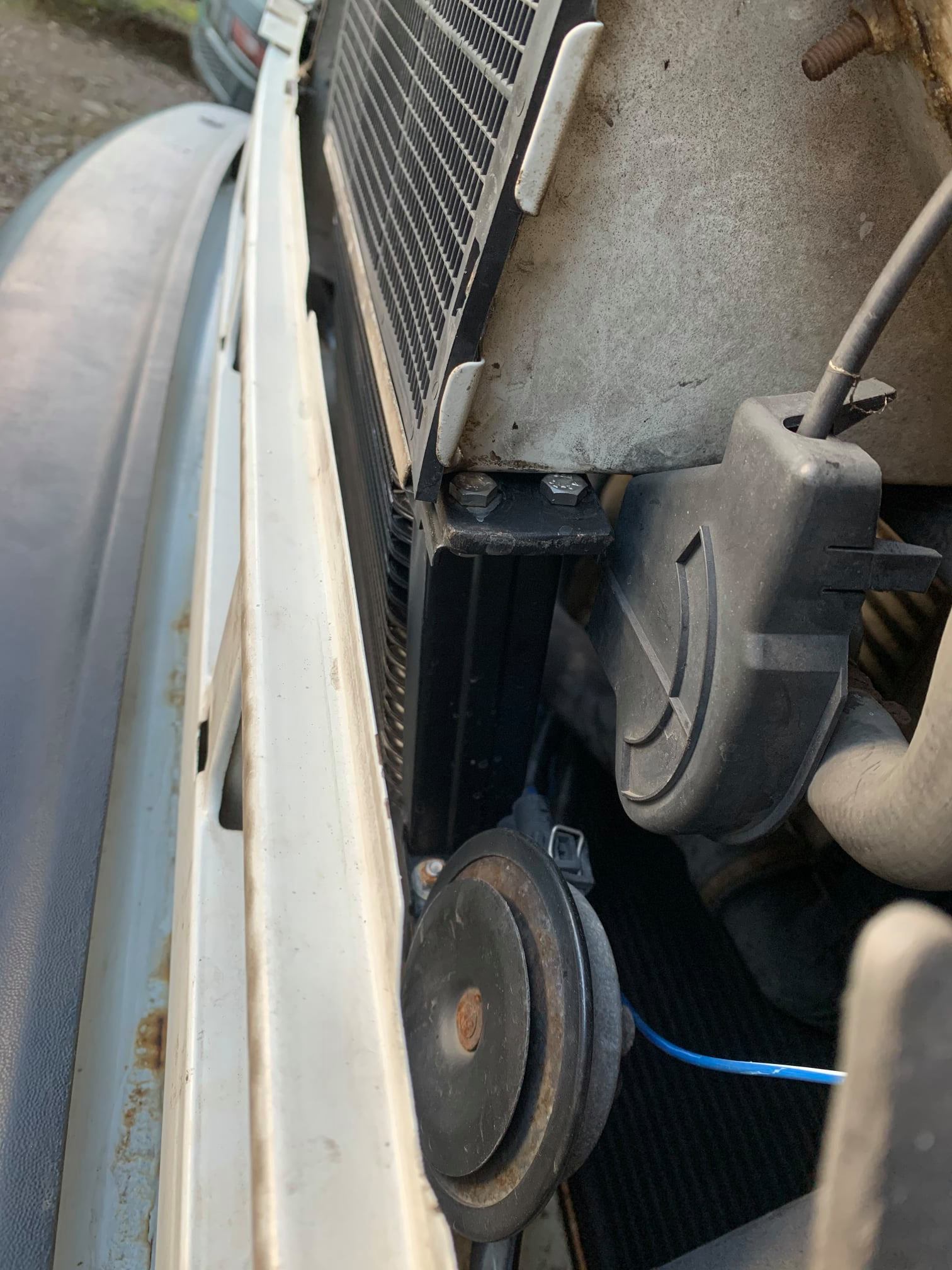
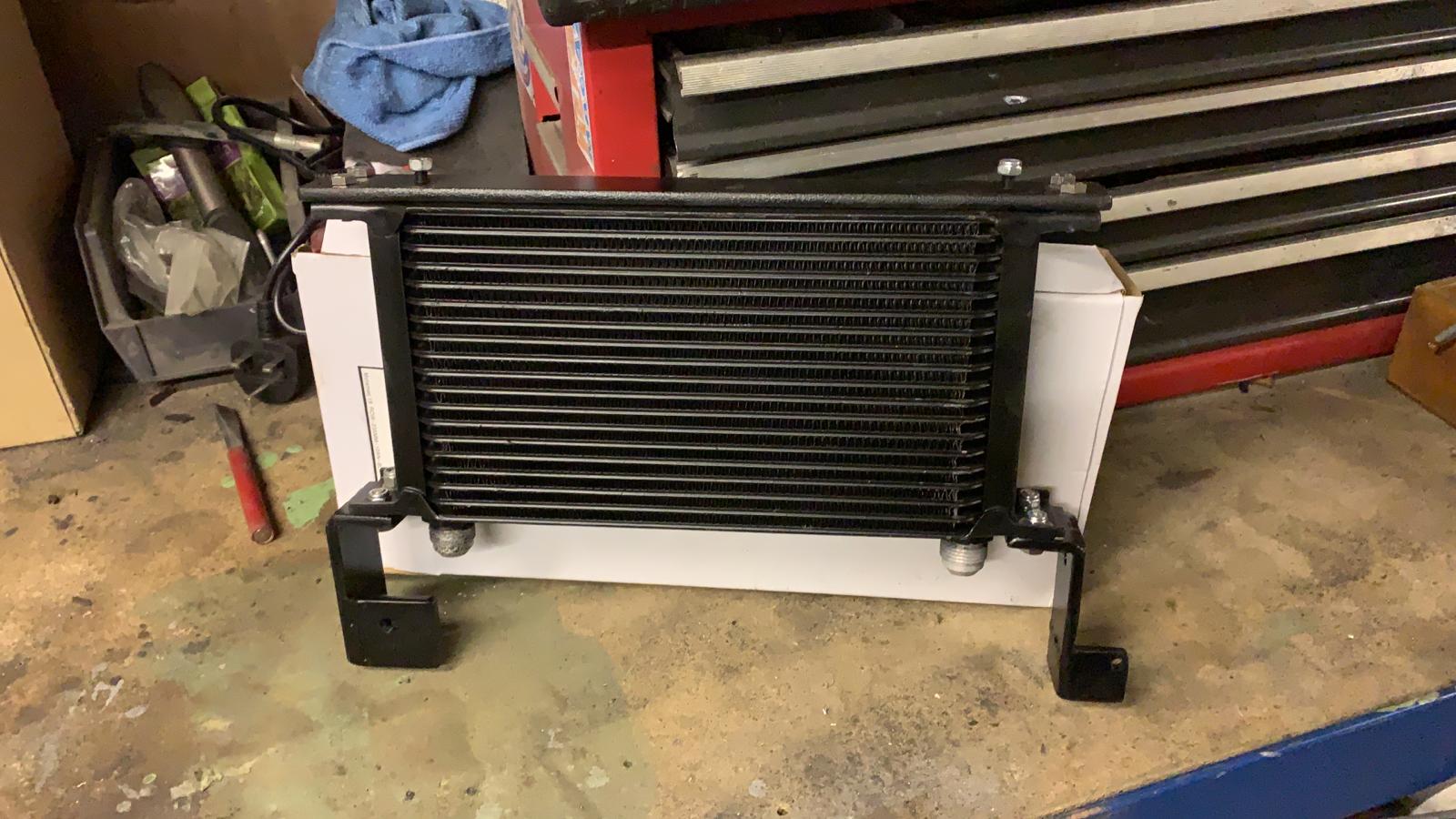
I used another sandwich plate which is the way to re-route the oil to the cooler. The ones I wanted aren’t ‘open’ all the time to help the oil to heat up quicker. They have a thermostat which gradually opens up until they allow full flow at a specified temperature. Again, there is some debate about what temperature this should be. I went with a MOCAL 92 degree take-off (SRK1-92)
You will also need pipework and various fittings to match whichever method you choose. The pipes themselves need to be pretty long to reach (depending on where you place the cooler). I had a mate make mine and they were each 1.25m long. These came with crimped ends or I suppose you could go for barbed fittings. To get the pipes from the cooler to the sandwich plate you’ll need to run them beside the radiator. It’s a bit of a squeeze to get the fittings through. I found that if I temporarily removed the mounting bolts on one side it gave enough movement to get them past. Avoid putting any strain on the oil cooler as the metal is thin. For my cooler I used a 19 row Motamec unit in a stylish black.

Now I had two sandwich plates; a double decker. I thought about whether this was good idea but then I saw that Mocal themselves sell a ‘spacer’ sandwich plate which is designed to help when clearance is an issue for the pipes. I figured it must be ok. I have the sender plate first and then the oil cooler plate. This means I can keep an eye on the oil temperature at the thermostat. At 92 degrees the ‘stat will be fully open and oil should be flowing around the cooler and keeping the temperatures within range. Everything works as it should.
THE TURBO
Now I turned by attention to controlling what the Turbo does. There are literally thousands of videos online which explain how Turbo Chargers work. Here’s one in case you’re interested. You can ignore the part about twin scroll setups, but we can always dream!
The Wastegate
As explained in the video; to prevent too much pressure, turbochargers have a ‘wastegate’ to ‘dump’ excess pressure. Incidentally around 0.7 Bar is stock,
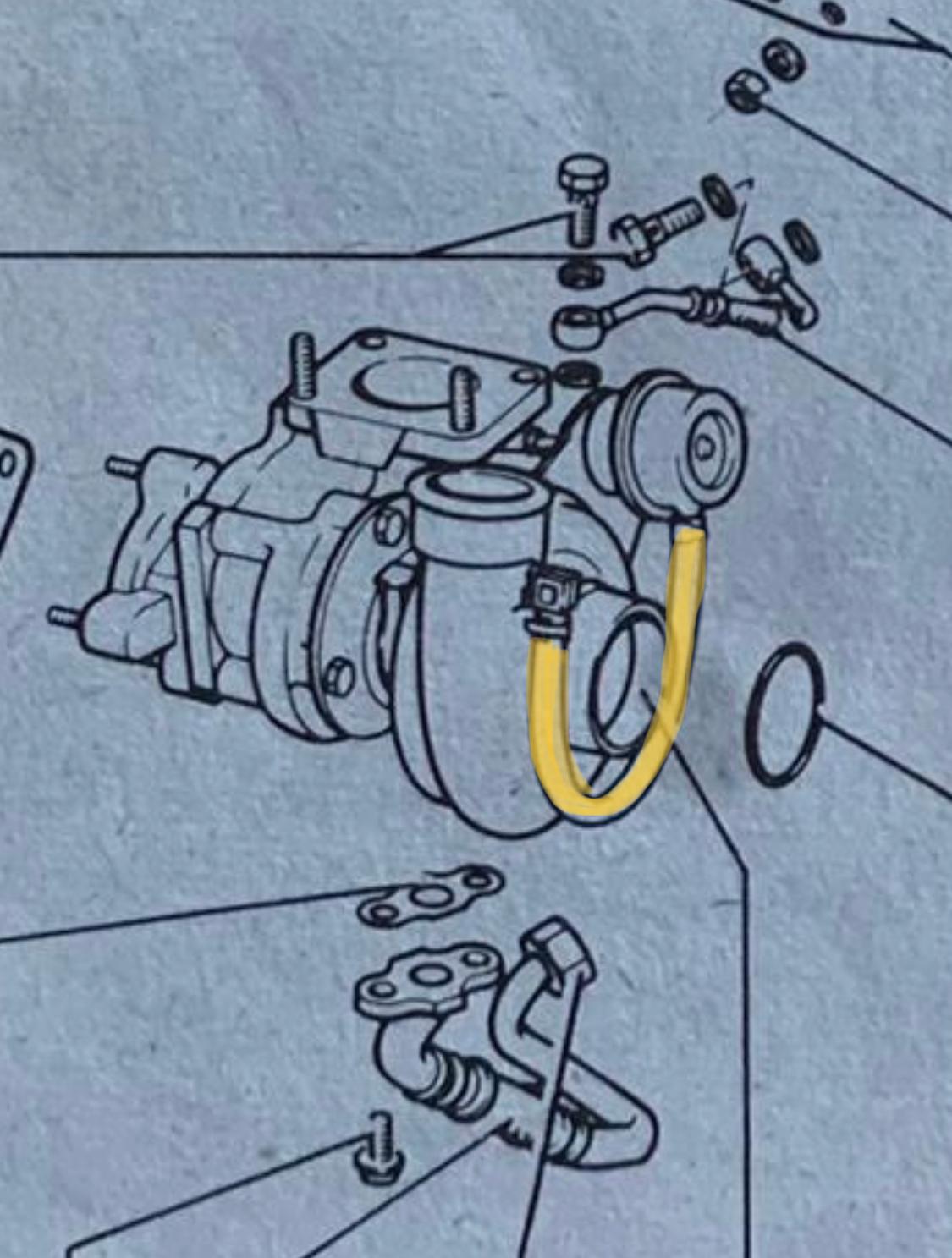
To do this there is an actuator which makes it happen. We want to take control over when the valve opens. One method was mentioned in the video I linked to earlier. This involves changing the length of the rod on the mechanism. I took a different (and easier and more adjustable) approach. When you were struggling to squeeze the Turbo Blanket over you would have noticed a short length of pipe (yellow on the diagram.)
This pipe carries boost pressure to the mechanism that opens the wastegate. In order to have control over this we need to add a ‘manual’ boost controller. These (again) come in all sorts of shapes, sizes and designs. Some are designed to allow some of the air to ‘bleed‘ out and therefore delay when the mechanism reaches its predetermined pressure. The second type is the ‘Ball and spring‘ type. Again, you can read up on how these work should you be interested. There’s plenty of material out there. I went for the second type.
Interestingly the instructions state that the way this works (A Dawes device) will be beneficial to any engine even if you aren’t increasing boost. Apparently it eliminates ‘waste gate creep’ (I’m assuming this is the wastegate gradually opening and allowing boost to ‘leak’). This sounds marvellous although I do wonder why VW themselves didn’t fit one it that’s the case!
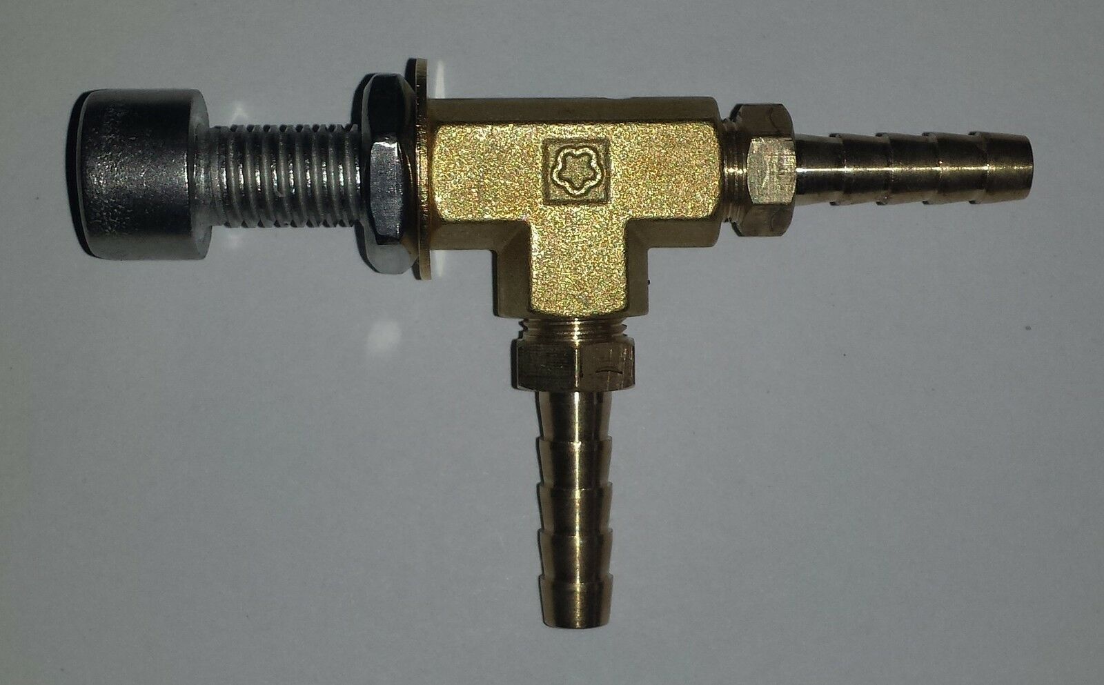
You can make these yourself using various brass fittings, ball bearings and springs. I’m very much a DIY kind of person but when you can buy these for £14 on Ebay I didn’t see the point!
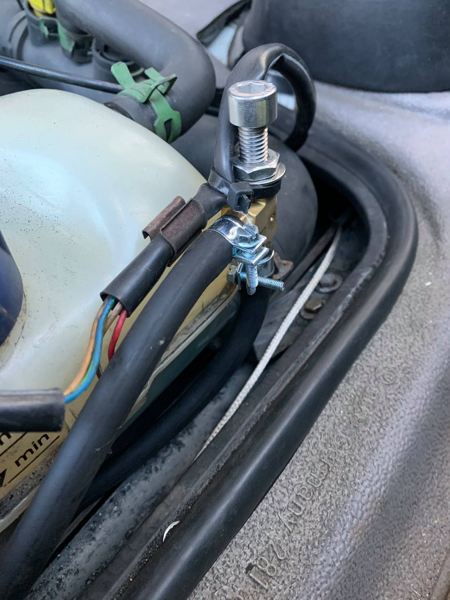
You’ll need some suitable pipe and clamps to. How much pipe you’ll need depends on where you choose to fit the mechanism. I’d try avoid having massive lengths of pipe. The idea is to run the longer pipes to and from your chosen location with the controller fitted. I put mine at the front of the engine and accessible through the ‘flap’. It’s not something you’ll be adjusting regularly once it’s all set up.
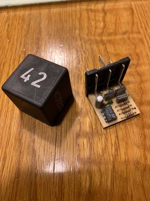
Relief Valve
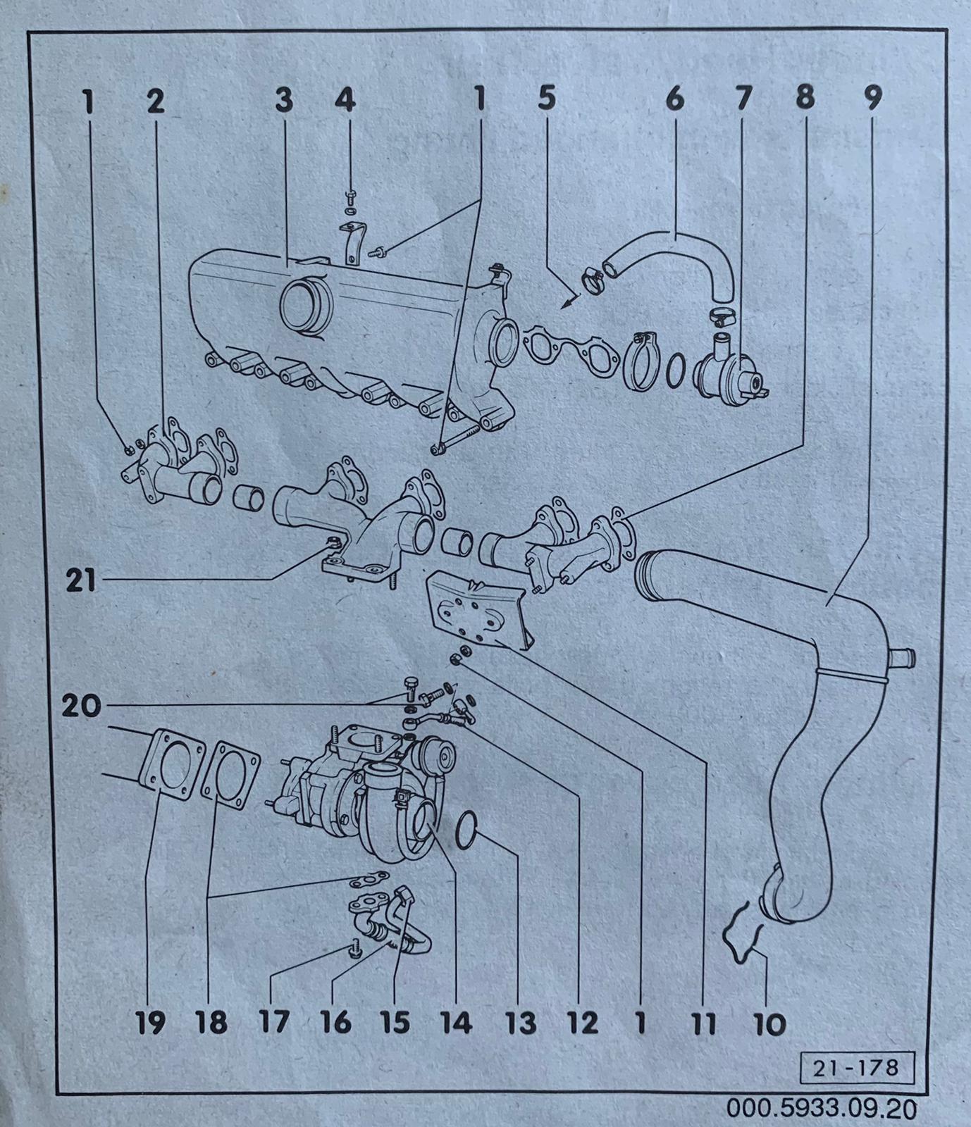
Now I turned my attention to the ‘Relief Valve’ which is number 7 on the diagram. A quick part number search reveals that this isn’t unique to the LT by any means. It’s purpose is to be a ‘back-up’ in case the waste gate mechanism on the turbo fails. It clamps onto the intake manifold and if the pressure inside it exceeds a pre-determined value it ‘vents’ to prevent over boost. The mechanism consists of a spring, a ‘valve’ and a screw. From factory on the ACL these are set to open at 0.81 BAR. I wanted the relief valve to open around 0.1 BAR above the wastegate value this needed to be looked at otherwise the relief valve will open before the waste gate did.
There are two ways to approach this. The first is to simply ‘delete’ the mechanism. This is as simple as removing the spring and replacing it with a short length of tubing such as fuel pipe. Then you can replace the screw and tighten the pipe against the valve and clamp it shut.
This method is a common one and effectively removes one potential failure point in the system. I was interested by the fact that it was adjustable by tightening or loosening the screw to increase/decrease spring pressure on the valve. You can of course stretch the spring to increase resistance but this is hard to know what you’re setting it to. The spring can then gradually lose tension again over time.
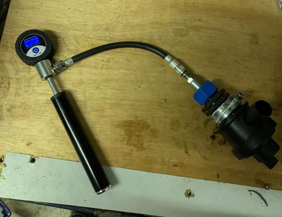
I set up a rudimentary test rig using a bike pump with a digital display and various pipe fittings and clamps. I was able to pressurise the valve and see when it ‘popped’. Even fully tightened up there wasn’t enough adjustment to achieve my goal. After some fiddling about I eventually found 6 ‘shims’ (washers) and 1/2 turn from fully tightened meant I could achieve the boost pressure I was aiming for. I’m planning on trying the ‘disable’ approach too at some point out of interest. You can play about with your own adjustments.
**After using this setup for a few years I decided to explore the ‘disable’ method. This just involves jamming the valve shut by putting something against it and tightening the screw.
I’m now at 1.2bar max and boost is maintained better at lighter throttle. You can choose your boost valve mod method. I’m sticking with the ‘disabled’ method 👍🏻**
Boost Ring
If you have looked into tuning up the Bosch diesel pump found in the LT you will most probably come across ‘Boost Pins’. I’ll come to these soon, but something else I discovered whilst reading up (especially in the Land Rover world) is the Boost Ring. Now this is tricky to fit in a Land Rover due to it’s location but a doddle in the LT. There’s very little ‘bolt on’ tuning equipment around for our engines so I was intrigued.
These have been used on tuned ‘Cummins’ engines for a while and are also know as ‘Dynamic Timing Spacers’. Apparently by allowing for greater advancement of timing at higher revs it can reduce smoke.

I fitted one because it was dead simple to fit and was easily available. I’m still not convinced it’s making any difference but it certainly isn’t causing any harm. It’ll stay on for now until I manage to get some time on my local dyno and see if I can back up the theory with some figures.
LDA Adjustment
Still here? Now comes the easy bit! The actual ‘tuning’ of the pump is really quick to do.
Here’s a video I found that clearly explains what the 3 mains adjustments to the LDA actually do (Star Wheel/Boost pin and ‘Smoke’ screw)
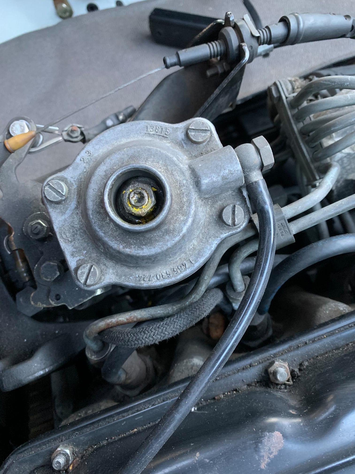
This is the part you do the adjusting at; the LDA. This (as explained earlier) controls the fuel entering the engine depending on how much boost is being generated. It’s a balancing act for the engine. There are three things you can adjust.
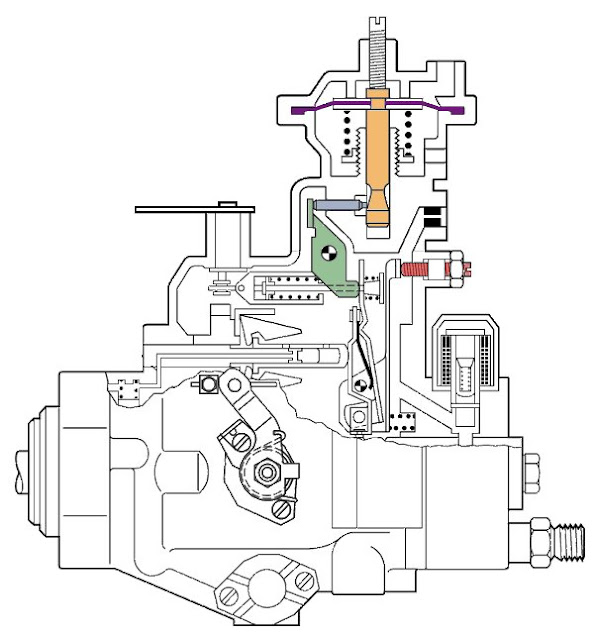
If you look at the cross section diagram above you can see the diaphragm (purple) with the boost pin attached (orange). Above this there is the ‘stop screw‘ (also known as the ‘smoke screw‘). Under the diaphragm there is a spring and platform upon which this sits is the ‘star wheel‘. By moving this you can change how long the spring is and therefore the preload on the diaphragm. On the bottom of the boost pin there is a ‘ramp’ and a pin that moves in and out according to the position of the ramp. The further ‘in’ the pin is, the more fuel is allowed to flow. The diaphragm is pushed down as the pressure from the turbo increases (along the tube we added the turbo boost signal T into.)

This animation illustrates this mechanism. ‘Einspritz menge’ is the amount of fuel injected. ‘Lade Druck’ is the Boost pressure.
You open the LDA up by unscrewing the top 4 screw. I’d definitely suggest making a note of where things start. I wrote down adjustments I made as I went along and also marked the diaphragm start position with a permanent marker. Once you have marked where the diaphragm is you can go ahead and move it. You might need to give it a twist and a wiggle. Once it’s out you’ll be able to see the star wheel.
‘Star Wheel’
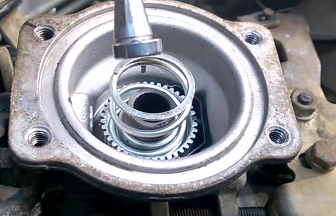
This is the platform on which the spring sits. The higher the platform, the more ‘preload’ there is and the harder it will be for the turbo pressure to push it down. You turn it clockwise (down) to decrease the preload. If it’s too easy then you’re going to get a load of fuel before there’s enough air to make it burn cleanly. Then you’ll get a load of smoke before the turbo spools up.
I turned mine clockwise three quarters of a turn (270 degrees)
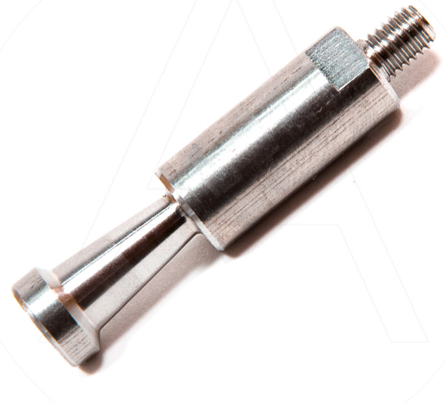
Boost Pin
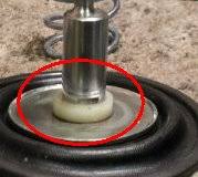
When you look at the pin which is attached to the diaphragm you will be able to see that the ramp isn’t the same on all sides. The angle of the ramp depends on which way the pin is rotated. The steeper the angle the quicker the fuel is delivered as it moves down under pressure. There might also be a nylon spacer on the pin too. This might have been removed already. This limits the total downward movement of the pin. If you have watched the tuning video at the start of this blog then you will have seen how you can adjust the thickness with sandpaper. I did this initially and then after a while I did what most folk do a removed it altogether.
You can buy aftermarket ‘boost pins’ (or indeed grind your existing pin yourself if your are that way inclined.) The aim is the same – to increase the ‘ramp’ to increase the amount of fuel delivered to the engine. These are a very popular modification especially in the ‘off road’ world.
These aftermarket pins aren’t adjustable (the ramp is ‘flat’) and the poorer quality ones can wear. You can end up with more smoke and high EGTs. As my overall aim was low down torque this wasn’t an avenue I explored.
I initially rotated the stock pin so the steepest angle faced the fuel pin (front of the van) . On our engines, this is pointing toward the front of the van. I marked mine with a pen and it lined up with the dimple on the diaphragm, but check your own as it might not. You can actually access the top of the LDA through the oil dip stick inspection flap at the rear of the engine cover without having to remove it. With a suitable sized screwdriver (and PLEASE don’t drop the screws!) you can adjust this in 5 minutes. I started at ‘MAX’ ramp, then tested and turned it a couple of degrees at a time (anticlockwise) and retested etc. You are looking for a compromise between smoke/EGTs and power. This is something that is unique to your setup but it’s really easy to adjust. I found that colder weather (and denser air) has an effect too. Whether or not you have an intercooler fitted with also dictate how much you can turn the pin. More on that later…
Stop (‘Smoke’) Screw.
The third thing you can adjust is the screw on the top of the LDA. You can do this without having to dismantle anything and access it through the ‘oil’ flap without having to open the engine cover.
This adjustment sets where the boost pin starts. The more clockwise you turn it, the lower the pin will ‘start’ at and the more fuel will be injected into the engine even before any boost comes into play. This is why it has the nickname ‘Smoke Screw’ because if you get carried away you will just get a load of smoke.
Mine had ended up 1 full turn clockwise but I have turned it back ever so slightly now. If you are getting excessive smoke before boost comes in then back this off. I get a slight ‘puff’ of smoke sometimes just off idle when the engine is cold. I don’t mind this as it soon disappears as the boost increases. If I pull away in second with a really light throttle I can sometimes generate a huge cloud 🙂
I Turned the Smoke Screw 1 full turn clockwise and then tweaked to taste!
Here’s the video I recommended at the start . It shows all of this again. It turns out that after all my fiddling I just about ended up with these recommended settings. Other than the fuel screw….
Fuel Screw
I removed the anti-tamper collar and gave the fuel screw a 180 degree turn clockwise. I got plumes of smoke. I tried 90 degrees. Still smoky. I turned it back to stock and I’m going to explore this again at a later date. This should be adjusted with caution.
Intercooler
Everything above is applicable to the all Turbo Charged 2.4 litre diesel engines. The main difference between those and the ACL is the intercooler.
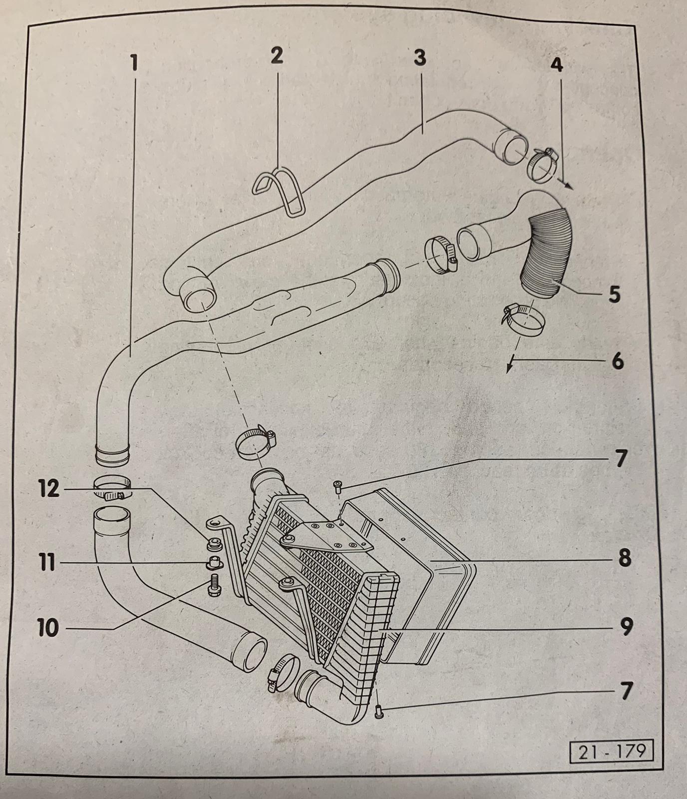
This intercooler is positioned in front of the radiator and the pipework runs from the turbo (5) , through the intercooler (9) and into the intake manifold (3). It’s an ‘air to air’ design. The purpose of the intercooler is to reduce the temperature of the air entering the intake manifold. Colder air is more ‘dense’ and therefore has more oxygen molecules to be burnt. This means a leaner burn. A leaner burn is a cooler burn. Exhaust Gas Temperatures will be lower as a result.
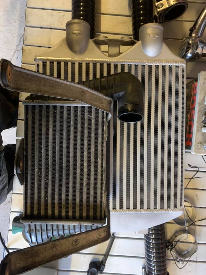
The stock intercooler is pretty small and has plastic end caps. It’s perfectly good for stock or mildly tuned applications. It is possible to fit a larger intercooler although there’s very little available as a bolt on kit.
I bought this ‘Darkside’ cooler which is actually designed for VAG (Volkswagen/Audi Group) Turbo diesels such as the Fabia VRS. It is much bigger than the stock intercooler and is fully welded rather than having pressed on plastic end caps. You can find other manufacturers making this style of intercooler online cheaper on Ebay etc for around the same prices. You pay your money and you take your chance. You can see there is a big difference in size between this one and the original.
Having removed and had a look at the old intercooler (which only requires the removal of a couple of hose clamps and a few bolts) it’s apparent that giving it a good old clean would help. Years and years of dirt clogging up the fins certainly won’t be aiding efficiency!
With some silicone bends, joins and a bit of time you could connect the larger intercooler to the existing pipework and you would see some benefit. However, I had decided I wanted to replace all the pipework with larger inner diameter (ID) pipework while I was at it. Getting the pipework alongside the engine and to and from the turbo and inlet with solid pipe would be difficult to say the least. I decided I would use flexible silicone hoses.
Once the old intercooler is removed, you simply undo the clamps at turbo and intake ends, unclip the rubber ‘ring’ (number 2 on the diagram above) and pull the old pipework clear. It’s a combination of rubber and metal pipework. I re-used the original rubber connection to the turbo (Number 5) but replaced all the hose clamps from start to end.
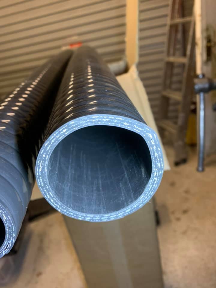
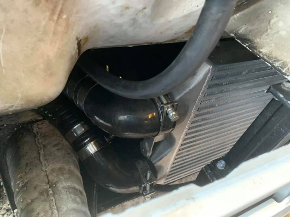
‘Normal’ silicone hoses would kink and crush easily and restrict air flow. These are Superflex hoses and are 6 ply (6 layers of silicone). They have a wire reinforcement, a smooth inner surface and a pressure rating of 10 bar. I used 51mm from the turbo to the intercooler and 60mm from the intercooler back to the intake manifold.
I’ll fast forward to the end; here’s an extremely high tech diagram of all the parts I ended up using…
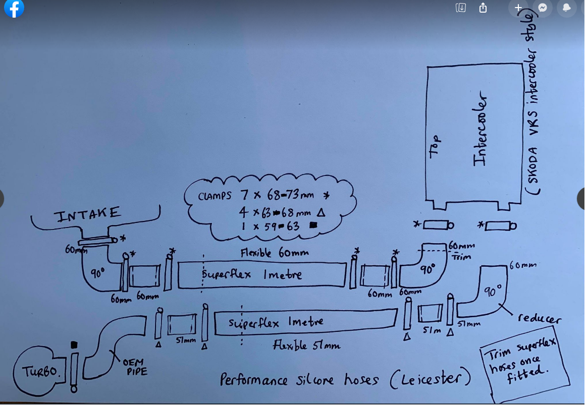
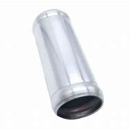
There are three 90 degree bends and a selection of metal joins (with the bead rolled ends to stop the pipes popping off) in two different sizes (60 and 51mm). All the sizes are in the diagram. The intercooler intake and outlet are 60mm. You’ll need to reduce this to 51mm for the turbo piping. This is achieved with a 60>51mm reducing 90 degree elbow.
I bought everything I needed from Performance Silicone Hoses in Leicester who make all their own products in house. They themselves say that they aren’t the cheapest compared to what you can find on Ebay or Amazon. I preferred to pay a little extra for some UK manufactured excellent quality products but you can find everything you need (except the flexible hoses) on the usual sites if you want to.
I used T-Bolt clamps throughout including the ones at the turbo and the inlet manifold. The measurements are all on the diagram (12 clamps in total). I bought Mikalor ones and they are excellent quality. Jubilee style clamps can damage the silicone hoses.
You will need to shorten the flexible pipes from their supplied 1m length. I’d get the ‘intercooler’ ends all joined up in position with the 90 degree bends and clamps all done and then cut these to length last at the ‘engine end’ to join everything up. You just put a clamp around the pipe where you want to cut, use a sharp blade to slice the pipe and then cut the wire reinforcement with some snips.
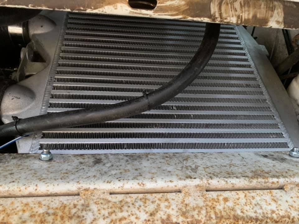
If you go for the VRS style intercooler there is really only one place to mount it. It fits snugly in front of the radiator. You’ll be taking this in and out a few times to get everyting measured up so I’d suggest you tape some cardboard over the faces as it’s easy to damage the fins.
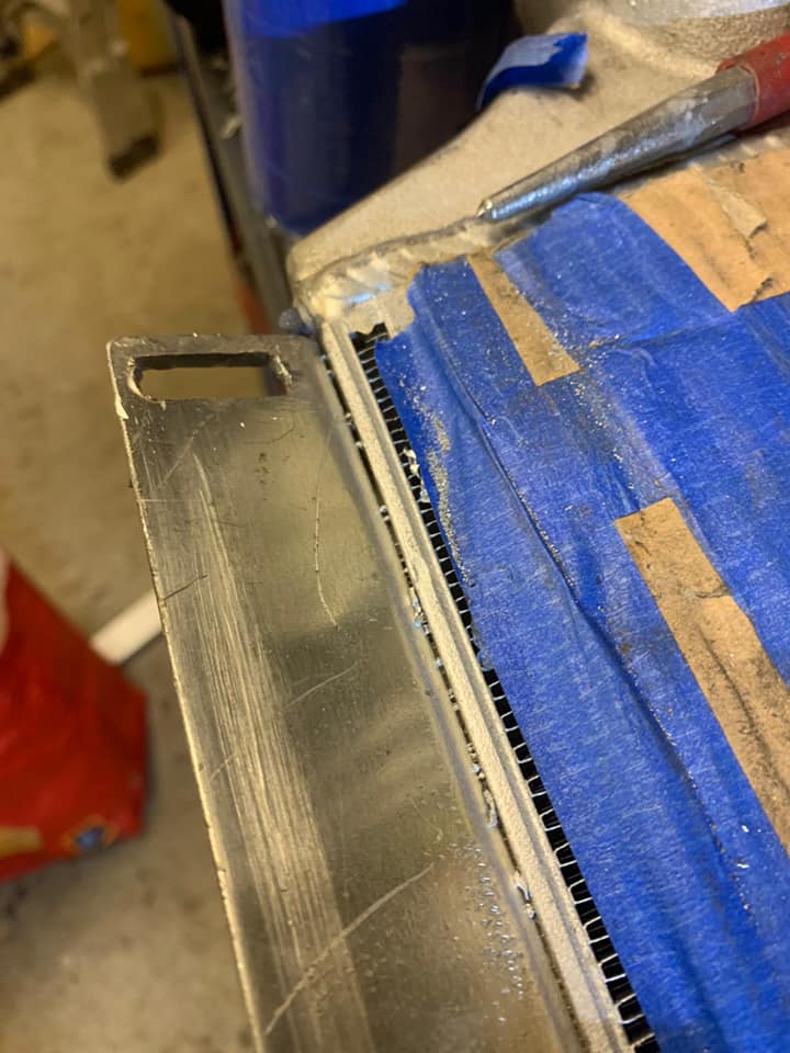
I thought up all sorts of ways to mount mine. In the end I had a mate TIG weld an aluminium angle to the bottom of the unit. It was hard to weld to so he ran the angle the whole length and welded the ends to the existing welds. Plenty strong enough! I added slotted holes and then drilled two holes in the cross member to bolt to. Access is tricky so once I’d worked out the height, I bolted M8 bolts to the aluminium and then through the cross member.
These two bolts combined with the support from the silicone hoses mean the intercooler isn’t going anywhere! If you don’t have the means to get some aluminium welded there are ‘factory’ M6 threaded mounts on the ends of the intercooler. You could make a bracket taken from these easily. You might have to reroute the alternator air intake pipe.
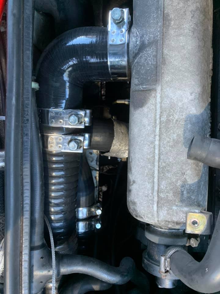
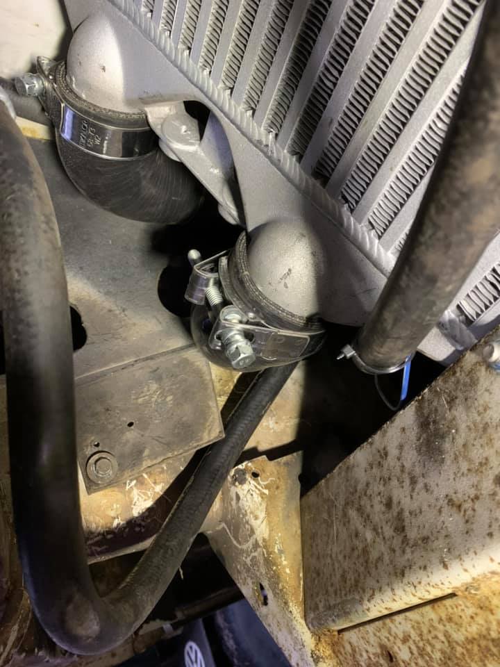
Once you have the intercooler mounted (put it as far over to the ‘right’ as you can to give you space for the hoses) then it’s time to get the flexible hoses routed to the engine. Grab the hoses and something suitable to help squeeze them through. I used a combination of WD40, Silicone spray and swear words. A willing and able helper would be useful too.
Start with the 60mm hose. This will feed through without too much trouble. You will be able to see where the old pipework was routed. Give it a spray and guide it through. There’s a lip on the bodywork it gets caught on but once it’s past that (and if you push and someone pulls) then it isn’t too bad. I tried all sorts of methods including loosening the radiator mountings. This worked well….until it was time to put the radiator back in position and it wouldn’t fit. You can imagine how happy this made me. I had to remove everything again and try again.
Now fit the 51mm pipe. You’ll have to get underneath and feed it along near to the other pipe. All I can say about this is….it WILL fit eventually but it’s not easy. Lots of spray and colourful language will see the mission accomplished. As you are going to be trimming the end anyway you can use some Mole-Grip type things on the end to help you heave it through. Where the pipework enters the engine ‘bay’ you’ll see the metal work is slightly shaped. This could gouge the piping. I used a metal bar the gently bend this out to avoid this. You might not need to. You’ll see what I mean when you start feeding it through.
Once it’s all through attach the intercooler 90 degree bends. Then trim the engine end and bolt everything up. It’s tricky working through the ‘letterbox’ access on the LT but very satisfying when you’re all done!
After some test drives I set my boost to 1.2 bar. I wouldn’t go past 1 bar without an intercooler. Compressed air get hotter and less dense (this is why hot air balloons float). Less dense means less oxygen which means a richer mixture which means higher EGTs.
If you’re looking to upgrade your ‘non-intercooler’ engine you could retro fit an ACL system with some ingenuity and modifications. That is of course if you can find the parts required. This is not something I’ve done but other’s have, so have a look around. There are aftermarket intercooler kits too such as the one available here on VOLT. This replaces the stock ACL intercooler and retains/adds to the original pipework.
Exhaust. I’m running a stock system at the moment, but I have plans for a stainless system at some point. I shall update when this happens. In theory – a better flowing (possibly larger diameter) system will be beneficial. Time will tell!
RESULTS
After some fine tuning I have settled on the adjustments outlined above. If you’re getting too much smoke early on before boost comes in then adjust the smoke screw.
So how does it drive?
It’s not ‘fast’ (but that was never the plan.)
I haven’t increased the overall fuel entering the engine by adjusting the fuel screw (but that’s not to say I won’t as some point.) What I have changed is when and how quickly the fuel is introduced according to boost.
Low down torque is massively improved. The engine can pull from low revs in high gears smoothly and strongly. There is far less gear changing. I can climb the hill to my house effortlessly with a van full of people and a dog and a full water and diesel tank. I can change from 1st to second and continue to accelerate without having to rev the engine to get the needle in the ‘zone’. Boost comes in well below this. Climbing hills is hugely improved. Cruising is better. Everything is improved!
With the bigger intercooler I have also upped the boost to 1.2bar (using the manual boost controller). EGTs are reduced, power increased and it sounds lovely! I might have a play with the fuel screw again now as I have more capacity to burn it. From my research 1.2 is my upper safe head-gasket limit. I’m in the process of researching gasket types and if (when) I need to replace mine I’ll upgrade accordingly. If you are sticking with the stock intercooler I’d say 1 bar max. If you don’t have an intercooler at all I’d be cautious with boost. Keep an eye on EGTs.
I’m yet see what the effect is on fuel economy but hopefully not having to rev the engine so hard will have a positive outcome. As long as the van is as efficient on fuel as it can be given its size and weight I’m happy. Not so much ‘miles per gallon’; more ‘smiles per gallon’!

Restraint needs to be shown when climbing lengthy hills. It would be tempting to try justifying to your spouse all the time and money spent by demonstrating how you can now climb gradients in 5th gear, but keep an eye on the EGT. I try and keep mine no higher that 600/650 degrees with brief visits to 700. When normally cruising they are around the 400 mark but can rapidly rise in high gears on hills under load. The answer is to stick in 4th gear where the revs and subsequent boost are kept higher and keeping the temperatures down.
With my setup of wheel/tyres and gearing my van sits at 60mph at 2500rpm and 70mph at 3000rpm . It’ll easily exceed 70mph but I choose not too! Since writing this article I have also had the propshaft reconditioned as there was a bit of a ‘wobble’ die to a worn joint. Something to watch out for!
Avoid ‘lugging’ the engine. This is of course true of any engine really! The increased boost with the bigger intercooler has brought these down too. I’ve recently bought a dual temperature gauge (intercooler in and intercooler out). I’m going to be doing some readings in different gears and hills to see what’s going on. I had meant to compare the stock and aftermarket intercooler performance but I got carried away fitting the new one!
As I’ve said before; I’m not claiming to be a pioneer in this and many before me have done the same (including those on the ‘Volvo’ scene). This is simply a collections of all this information and my personal experience in one place which I hope someone might find useful. If you have any questions you can find my on the VOLT and Florida Facebook pages. Above all….have fun!
Cheers
Karl
Been following this very informative feature, currently I am restoring my lt van engine similar to yours and I added an intercooler and oil cooler hopefully to add a bit of power to the engine, well I’m doing everything according to your explanation, I wish to enquire weather these last years since your modifications weather you had any issues or made other adjustments,I have made a lot of effort to get the engine in nick Co diction and while it’s still on the work bench any mod, are easier to implement, thanks for your advice. Joe