This document is not a “How To” document but meant as a guide for those who wish to attempt to repair this valve. I can not be responsible for inaccuracies contained within or problems that may occur with the end result.
A pre MOT health check on my 1996 LT35 panel van showed a leaking load sensor valve. Evidently there are none available anywhere, even in Germany. There are suggestions that valves from other vehicles can be adapted to fit. This sounded like a major modification to me, because if not done correctly it could result in the back wheels locking up and inducing a skid. If this caused an accident and the insurance company does not accept the modification, it will be your fault. I rejected this solution because of that. Getting a modification like this approved could be a headache. The alternative was to carry out a repair on the old valve. A Google search brought up a link to a repair on a German site:
http://www.lt-forum.de/dokuwiki/doku.php?id=start:reparaturtips:bremskraftregler_instandsetzen
This is excellent. Hit the translate to English Google button and it will get it mostly right. This inspired me to try a repair. I had nothing to lose after all without this part the van is to “slaughter” ( Google translation ) anyway. Here is the way I did it blow by blow.
Jobs in order:
- Pressure wash underside of van.
- Jack the chassis up away from the axle and support; this slackens the spring on the valve. If you are a reasonable size you can leave the wheels on the ground and chock them. There should be plenty of room to work underneath.
- Take the valve off. I gave it a good wire brushing and a soak in penetrating oil then slackened off the adjuster on the top of the spring to relieve the tension on the spring. I found a tight fitting open ended spanner to undo the 3 brake pipe unions. I did not block the brake pipes as I thought I would replace the fluid that runs out. If your fluid has been recently renewed you need to block the pipes with something. I used a silicone rubber sock for this.
A quick spanner job had the complete unit off and onto the work bench. The rubber dust boot was taken off and the spring retaining clip saved. - Clean and disassemble. The bleed nipple was soaked in penetrating fluid again. The unit was held firmly in a solid vice and the whole unit heated with an electric paint stripper blower gun. Do not get too hot, it needs to be hot too the touch only. There is plastic inside the body of the valve that will be damaged with too much heat. The nipple was then teased into submission by the use of a tight fitting ring spanner and lots of small taps with a small hammer on the spanner shaft immediately after heating and while it is still hot. Perseverance wins. It is the gentle vibrating of the hammer taps that eventually loosens it. If you break it off then it is the drill and tap technique as per above link. Next undo the large hexagon plug on end. Again hold firmly in vice, heat as above, and tease undone with a good fitting ring spanner and gentle taps with a hammer. Removing this plug revealed a thick creamy substance like jelly behind it, I think it should have been brake fluid, I can’t see how the unit could work efficiently like this and I guess that my valve hadn’t been working properly for years!! I could not move the piston behind it and it appeared to be seized up.Next job was getting the inside bits out. This is where the grease nipples come in. I bought 10 nipples from ebay for £3.48. I am not sure whether they are straight thread or taper. Taper thread can damage the threads in the body if tightened. I put mine in finger tight plus a gentle tweek with a pair of pliers. I didn’t mind if they leaked a bit but damaging the threads is a no no. Put one in each of the brake pipe holes, 3 in all. The internal pistons will be pumped out hydraulically with a grease gun from these nipplesBefore pumping the pistons out there is an internal sprung wire snap ring that needs to be taken out. This holds the piston in on the lever end of the unit. The piston needs to be compressed to reveal it and held in to take the snap ring out. I made a simple jig from scrap wood and a piece of M6 studding.
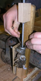
Figure 1 Removing the snap ring.
The piston was free so could be pushed down by hand easily. It was kept down by a nut on the studding. My son and I wriggled and jiggled with 2 small flat ended screwdrivers for 15 minutes and still could not get it out. It would move round go down and wedge but not move upwards and out. We had a cup of tea and cooled down!! I crept up on it a few minutes later, in with the same screw drivers and it popped out straight away. I can only think it is the element of surprise!! Don’t loose the snap ring. It has to be put back in on assembly.
Now to pump the pistons out with the grease gun. This is the way I should have done it. First pump out the piston behind the hexagon nut. To do this have the unit in the jig with the hexagon nut off and a pack (shaft of a large screwdriver) underneath it where the nut was. This will allow any grease to ooze out. Keep the lever piston securely in with the M6 studding and pump the centre nipple with grease. This released the ceased piston with a pop and yep, it hadn’t moved for years. The unit can then be taken out of the jig and the hexagon put back on finger tight.
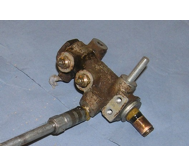
Figure 2 Pumping out second piston.
The lever end piston can now be pumped out. I took this lever end piston out first and then had to put it all back together again to be able to pressure the piston out at the hexagon nut end.
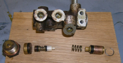
Figure 3 Internal bits in order
- Cleaning the grease from all of the parts and inspect. The cylinder looked to me to be perfect with no blemishes at all. The O rings looked complete but tired. I decided to renew the O rings. The correct size of O rings needed are stated in the Wabco manual for the valve and are large piston 2.4 X 13.3mm bore, smaller brass piston 2.4 X 5.3mm bore and the one on the plastic piston is 2.4 X 4.3mm bore. These are all available online from WWW.simplybearings.co.uk Bought in packs of 5 and are classed as Nitrile 70.
- Replace the O rings and seal. The new O rings went on the two brass pistons easily at hand temperature without any problem (a bit of silicone grease helps here ) however the small one looked impossible to get over the plastic piston to it’s seat. The German site mentions about egg shells and hot oil, something obviously went wrong in the translation!! I decided we needed a small carrot to put over the end of the plastic piston to slide the ring over. My wife came up with the idea of using a hard wax crayon found in the children’s toy box because it has a slippery surface. (I would have used a piece of wood). The crayon was turned up to be just a tad larger that the plastic piston. I used a lathe because I had one but I reckon you can whittle it away with a pen knife. I drilled a 4.5mm hole in the large end to slip over the nipple bit of the plastic piston and placed it in position.
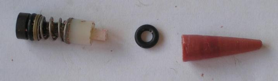
Figure 4 Before putting O ring on.
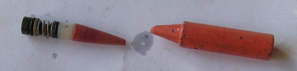
Figure 5 O ring on and spare crayon.
The whole assembly was then smeared with silicone grease. A saucepan of water was heated up on the hob and a small metal cup with some vegetable oil floated in it.
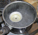
Figure 6 Cooking up O ring in vegetable oil.
When oil was hot (not boiling) the small O ring was dropped into the vegetable oil for about a minute. I took it out with a pair of tweezers and slipped it on the end of the carrot. The ring expanded easily and slithered up the carrot with minimal pressure straight onto the plastic plunger. Then just pull the spring and plastic seating washer back and let it fall in. YES !!!! I didn’t expect it to be that easy. Of course the wife took the credit.
The cup/U seal was loose in the seating. It should be a tight fit. This is where the fluid is leaking from so needs to be replaced. This can be sourced from Past Parts of Bury St Edmunds http://www.pastparts.co.uk/ Telephone 01284 750729. Ask for part number S9343. This is OK using Dot 4 brake fluid; if you use anything else ask their advice as to compatibility. This firm also supplies a perfectly fitting rubber dust boot, part number PPL 17-7553. I did not put the new cup seal on the piston because I had to take the piston into Past Parts for them to find a seal and they put the new one on prior to collection. - Assemble Before final assembly make sure the small air hole under the Wabco name plate is clear and put some more felt in it. Evidently the valve needs to breath. I found a couple of small self tappers to hold the plate back on and put a small bit of epoxy in the rivet holes to give the threads a key.Next the cylinder and pistons was smeared with silicone grease making sure there were no lumps left inside that could foul the passages. The pistons were pushed in. It was noticed here how easily the large piston with the O ring on it moved with just finger pressure against the spring where as it had to be forced to move with hydraulics on disassembly. The valve was put back into my wooden jig to get the snap ring back. Put the plunger in and put on the new dust boot. Put the lever system back on with a bit of grease on the pin.
- Install valve back on van. Putting the valve back on the van was tricky. I found the best way is to A) get unions 11 and 12 started away from the bracket but not tightened. B) Slide the valve into place while locating union 21 (feed to rear brakes) and get union 21 started. C) Put in the two 8mm bolts holding the valve to the bracket and tighten. Then tighten all unions.
- Bleed brakes starting with the valve then back wheels and then fronts.
- Adjust. Hook up the spring and slide spring adjuster up the slot to the required position. See notes below. It should be set up by an expert, in my case the MOT man.
NOTE this is my own personal experience, Just after putting this back together I had to do a bit of heavy braking on a wet road. I managed to lock up the back wheels, I had the spring adjusted to three quarters up the quadrant. These are my thoughts on trying to understand the setting of this valve and are a guide only.
A) When the van is fully loaded maximum brake pressure is needed on back and front wheels.
B) When the van is empty more pressure is needed on the front brakes and less on the back. (To avoid back wheels locking up)
C) The valve has a piston (the one with the cup seal on it) that is held in via a plunger which is pushed in by the operating lever. The in position allows maximum pressure to front and back wheel alike. This is the heavy load position. The out position vectors more fluid pressure to the front wheels and less to the back. This is the light load position. (Less braking on the back wheels.)
The piston can only be pushed out with pressure from operating the brake pedal and is relative to tension on the large external spring. The tighter the spring, the more the pressure on the operating lever holding the plunger in, the harder it is to force the piston out. We need the piston to be held in for a heavy load and are allowed to move out with a light load.
D) The large external spring connecting the operating lever to the back axle is under tension and holds the piston in.
E) When the van is loaded the chassis and axle moves closer together tightening the spring, this holds the piston in tighter stopping it from moving to the light load position. In other words it remains in the heavy load position longer under pressure from the brake pedal.
When the van is empty the axle moves away from the chassis slackening the spring. This allows the piston to move out to the light load position earlier when braking.
The van passed the rolling road test for the MOT & the repair seems to be a success. The cylinder walls were in reasonable condition, if they were damaged in any way then it could have been a different story. Past Parts of Bury St Edmunds will supply the seal and dust boot and have suggested that they may do the repair for you. Give them a ring on 01284 750729. This company can also repair your master cylinder and brake callipers.
“Keep em rolling”!!!